When you click on links to various merchants on this site and make a purchase, this can result in this site earning a commission. Affiliate programs and affiliations include, but are not limited to, the eBay Partner Network.
JY-15B Time Control Timer Board Power Supply for coin acceptor selector
Description
*Newest version of software!!
*This is used for power supply time control.
*Can be used with a coin acceptor or other devices that can
output pulse signals.and you can set up for what values to startyour machine!!
*Suitable for any kinds of automatic control devices such PCs.
Input Voltage
DC+12V
Standby
Display shows:00:00, rely: Normal Open (NO)
Accumulated time
Yes, add time if receive signals again when time is running
Max current load
15A
How it works
Mode 1
Time runs down after receive signals-> Display shows remaining time and supply power to device-> it cuts off power after time runs out
Mode 2
(Connect a button)
Display shows remaining time after receive signals-> push button start-> time runs down and supply power to device-> it cuts off power after time runs out
Pause
(connect a button)
Push button pause: it cuts off power when pause, display shows remaining time. Re-supply power after push button pause again
Operating Mode
Please reference to page 2
Connection Example
Please reference to page 2
Features
(1)Controls electrical devices ( TV, Massage chair..) power.
(2)Suitable for public place location and most of electric device control,
for example:PCs,washing machines,dryers,massage chairs,chargers,etc.
(3)AC 1250W/DC 500W electrical relay capacity.
(4)Digital timer: rate adjustable by owner through three simple push button switch.
(5)The time can be set by seconds or by minutes.
maximum time : there are 2 version of software
•99:00 (minutes:seconds)or•99:00 (hours:minutes)
(6)Control time by seconds-minutes or minutes-hours.
(7)Accumulate time when signal inputs.
(8)Timer control board with coin acceptor operates with 12V DC power.and has
the LED to show the Time left.
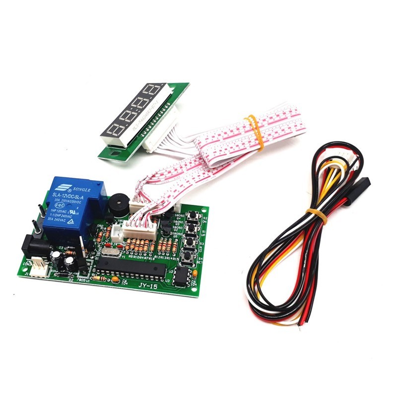
1: Display 2: 40 cm white lead
3: Switch control device power wire:
control “L” or “N” of device power wire
4: AC jack-5.5mm*2.1mm
5:YELLOW: DC12V,WHITE: input signal,BLACK: GND
6: START for mode 01:02 7: Pause
8-11: Button S2, S1, S3, and S4
Max Time:99:59 Display: 99:59
A: 2 digit: either HOUR or MINUTE
B: 2 digits: either MINUTE or SECOND
Please following page to adjust Time type.
Setting:
Please follow CODE ON DISPLAY and use button \"S1\" and \"S2\" to set up number
- INPUT SIGNAL QUANTITY AND TIME
- Please press button \"S4\". “B” flashes. Please set up INPUT SIGNAL QUANTITY to active device (01-50).
- Please press button \"S4\", “A” flashes. Please set up TIME (01-99).
- Please press button \"S4\", “B” flashes. Please set up TIME (01-99).
- Please press button “S4” 4 TIMES.
- Please set up TIME for Warning Sound.
- Please press button \"S4\" to finish.
PAGE-2
- GIVEN TIME:Add time by free if input signals reach SETTING RATE during time is running.
Example Setting: input signal to active device: 01, input signals for given time: 03 give time: 02:10
Add time “02:10” free if receive “3 signals” during time is running.
- Please press button \"S4\" 4 TIMES. “B” flashes. Please set up RATE OF INPUT SIGNAL QUANTITY.
- Please press button \"S4\", “A” flashes. Please set up GIVEN TIME.
- Please press button \"S4\", “B” flashes. Please set up GIVEN TIME.
- Please press button \"S4\" to finish.
Please follow table to set up operating function:
- Please hold on button \"S1\" and \"S2\" simultaneously for 3 seconds to get intoMODE SETTING.
- Please use button \"S1\" and button \"S2\" to set up number forCODE
- Please press button \"S4\" to switch to next code
Function
Code on Display
Description
A
B
Running Time
01
01
Time runs down without pressing button
02
Time runs down by pressing button
Time Type
02
03
MINUTE: SECOND
04
HOUR: MINUTE
Memory
03
05
Yes: Remaining time keep running after power off and on
06
No: Standby power off and on
Back to standby
04
1-30
user has no action after push buttons or receive signals in setting time
Default: 01-03: Bold and base line. 04: not use the function.
Specifications
The timer control board for any electrical load does not exceed the following:
•DC 30V,AC 250V,Current 7A
•DC 28V,AC 250V,Current 5A
•Size:91.0mm X 54.30mm
•Unit Ship Weight:0.25kg
Connection example:
The Package included:
(1) 1 X Timer Control Board
(2) 1 XPower wire andSignal wire
(3) 2 X Connect USB wires
It